On twist center and shear center

There has been discussions on where the twist center actually is. Following my previous post A Thin-Walled Circular Section Under Bending where I proved the shear center being the opposite of the slit for open C sections, I came across the paper https://journals.sagepub.com/doi/abs/10.7227/IJMEE.31.3.4 by Prof. Li. The paper claims that the twist center is the centroid of the cross-section.

However, this conclusion caused a conflict with the knowledge that twist center coincides with the shear center. If we take the conclusion of the paper that the twist center always coincides with the centroid together with the conclusion that the shear center and twist center always coincide (proven by lots of scholars, including this paper from many decades ago The Center of Shear and the Center of Twist” by Weinstein), this would imply that the shear center is always at the centroid, and this conclusion conflicts with what I found about open C sections as proven in the other post I mentioned.

To resolve this conflict, I did the following derivation on the location of twist center using the same notations introduced in Prof. Li’s paper.

twist_center_derivation.pdf (2.2 MB)

The conclusion from my derivation is that we cannot conclude twist center coincides with the centroid because Eq. (12) and Eq. (20) are essentially equivalent, so they cannot be combined to obtain Eq. (21) in the paper.

In case I made a mistake in my derivation, please let me know. If you have comments on the location of the twist center or you have insights on how to resolve this conflict, please comment below. Thanks!

Dear Sichen,

Thanks for your recent email and kind invitation to this platform. As you invited me to this platform, I assume that you do not mind my responding to you openly on this platform. Another consideration is that our discussion might help others interested in the topic. A further reason is that if I was proven wrong, it would be good to admit my mistake openly, so that others would not be misguided anymore. This is of course a pre-emptive assumption. Having went through my 2003 paper and recovered some of lost memories, I am still convinced what I published in that paper represented a correct account on the subject of twist centre.

Let me take the discussion a step back first. Before any discussion starts to make sense, it is crucial that the definition of the subject, twist centre in this case, is made clear. Unfortunately, once one started searching for its definition, confusion will arise, since it is not unique.

As far as Saint-Venant’s torsion problem is concerned, as presented in most textbooks of Theory of Elasticity, the concept of twist centre is not necessary, as the problem can be formulated completely without resorting to this concept. All the formulation required is an origin of the coordinate system. It is the ORIGIN of the coordinate system as it is called. If one wishes to call it as a twist centre, it is perfectly legitimate. As far as the formulation is concerned, the location of the origin of the coordinate system can be arbitrarily placed and the theory itself does not have any restriction on it. It does not have to be inside the cross-section of the prismatic bar under consideration.

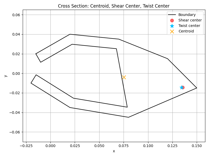
Given the arbitrariness of the twist centre, it can be SELECTED to suit one’s taste. Since the shear centre of any prismatic bar can be uniquely defined, many decided to select the twist centre to coincide with the shear centre, Timoshenko being one of them, followed by many more. In fact, if one did not place any further restriction to the definition of twist centre, there is absolutely no need to prove or determine the location of the twist centre. Any point can be proven or determined to be one, including the shear centre, as well as the origin of the coordinate system, of course!

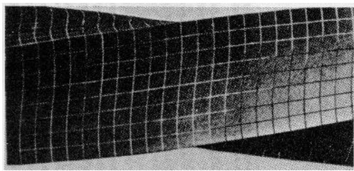
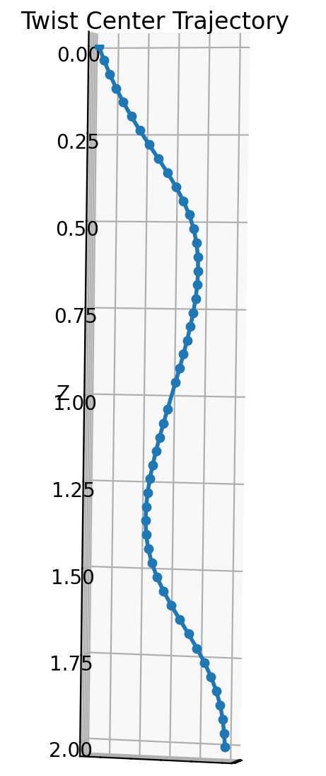
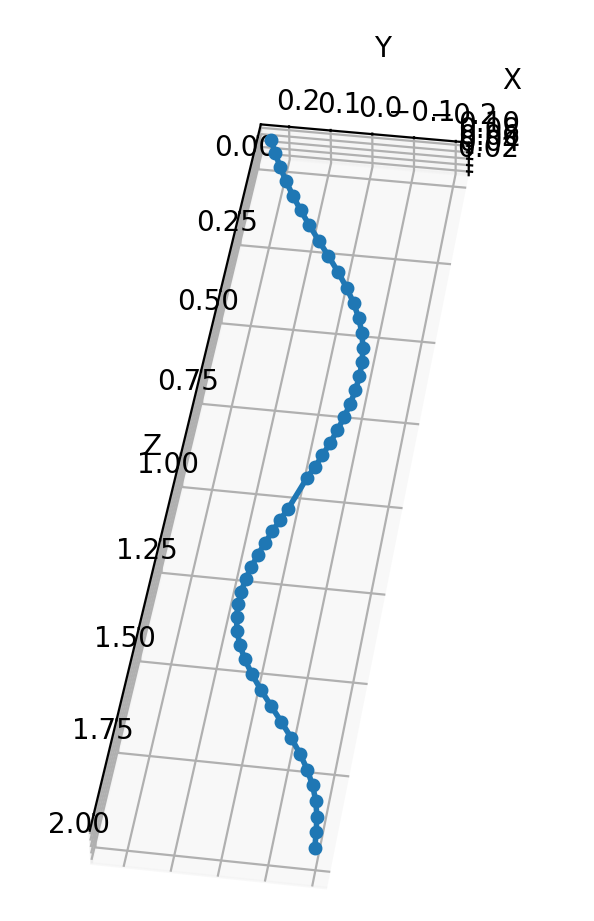
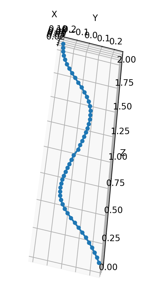
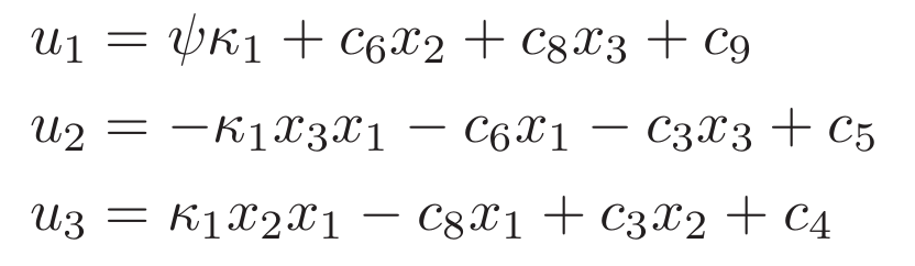
The formulation of the torsion problem is primarily a process of reducing it from a general 3D problem to a 2D presentation after the introduction of a certain pattern of the deformation, characterised primarily by the warping function. Although the mathematical problem to be solved has been reduced to a 2D form, if one did not lose the 3D sense of the problem, he/she could reconstruct the configuration of the deformed bar in his/her mind. If anyone finds it hard to visualised it, reference can be made to the picture of a deform bar of square cross-section as can be found in Timoshenko’s textbook. I have a lot of similar pictures but not sure if this platform allows them to be uploaded. In the deformed bar, each longitudinal fibre gets twisted and forms a helical path in 3D space. A longitudinal fibre in space corresponding to a point on the cross-section of the bar. If an arbitrary point on the cross-section is selected as the twist centre, it will alter its location in space from cross-section to cross-section due to deformation. To ease this uneasiness, Timoshenko argued, as many others, such movement from one cross-section to another amounted to a rigid body motion, which is true under the small deformation assumption.

If one is happy with such an argument, the case should settle here at this point.

However, the practice and spirit of science is searching, and searching until one is satisfied. My searching was inspired by a further question as I stated in my 2003 paper: Amongst all longitudinal fibres, within or outside the domain occupied by the bar (in the case of outside, the empty space surrounding the bar could be considered as continuous extension of the bar without contributing any stiffness to the bar), there is one and only one fibre that remain straight. Where should this fibre be located? What was proven in my 2003 paper is that this fibre passed the centroid of the cross-section. In other words, when a prismatic bar is subjected to torsion, the trace of the centroid represents as a single longitudinal fibre that remains straight. Without overstretching, this observation remains true even when the deformation goes beyond infinitesimal regime, although this would be another subject.

If one had selected the twist centre for any particular reason, given its arbitrariness, it should not offend anyone, except admitting that its spatial location after deformation would vary from cross-section to cross-section, which should hurt anybody.

However, if one does not have any particular preference, he/she might as well select the centroid as the twist centre. At least he/she is assured that it is always there at the same point after deformation over all cross-sections. The choice rest squarely with the users, of course.

As I said earlier, without further restriction, the location of twist centre is arbitrary. However, if one adds a meaningful restriction, it could then be uniquely determined, coincidence with the shear centre being one of such a restriction. Apparently, by introducing a different restriction, one could end up with a different location of the twist centre. Taking centroid as the one is simply another illustration of the lack of uniqueness of the definition. Through the illustration, it has also been made clear that the lack of uniqueness could be rectified by additional restrictions.

If one reads carefully, in each account of twist centre discussion, if any of them claimed having determined a twist centre, there was an additional restriction associated with, explicitly as I did in my 2003 paper, or implicitly in which case the would be the responsibility of the readers to identify it. Otherwise, picking up a different point, the prove would apply equally. Unfortunately, not all authors were perfectly clear what the additional restriction they had introduced. This is obvious the reason why confusions and controversies often arise on this particular subject.

Having taught theory of elasticity for more than 10 years with the torsion of prismatic bar as one of my favourite topics, I perceive that I had reached to bottom of the problem. Having said so, I am eagerly looking forward to any disagreement proving that my perception was wrong. I will never consider it as any kind of offence or disgrace of mine. Instead, I will be grateful for the stimulus to search for truth further deep down by me or others, like you.

Hope the above elaboration helps.

Kind regards,

Shuguang

@epzsl2 Thank you Prof. Li for your detailed, kind response! This interesting topic was brought up by Prof. Yu @Wenbin as it seems confusing to us that twist center can have different locations. As you pointed out the twist center has a loose definition, and to have a unique twist center, different people introduced different restrictions, which is the cause of conflict as different restrictions lead to different answers.

Comparing the 2003 paper to my own derivation, I do believe that one more constraint has been added to locate twist center in the paper. My own derivation does not lead to the conclusion that twist center has a unique location.

Finally, one interesting question is, if twist center is truly arbitrary, why do we define twist center? And what is the significance of twist center if the location is arbitrary?

If anyone has comments on this, feel free to join the discussion!

Also this platform does allow uploading pictures, you may drag your pictures in your text box and it will be uploaded to the platform.

That was quick! You have asked an interesting and legitimate question why on earth the concept of twist centre should be introduced if it is not even unique. My understanding is that it is historical. History could be very very shorter if we followed a straight path backwards. Unfortunately, from the far end of it, nobody knew which path it should or would follow. There had been great people in the past they were so gifted that they could foresee a stretch of the path ahead correctly. Whilst one might admire how lucky they were, they could bear more responsibilities on the other hand when they got a thing wrong as it would misguide a lot of people following him. Luck always comes with potential punishment. If one started to abuse his/her luck, the punishment would be imminent, I believe. Please therefore be content with being an ordinary guy with only as much gift as you could enjoy without having too much to spoil. Sorry for being philosophical here, sign of aging!

Back to the twist centre, if one cared to dig, I believed it probably did not come naturally with the formulation of the torsion problem. People might have been inspired by the fact of the existence of shear centre. In fact, even the concept of shear centre, it wasn’t established as straightforward as one would like. As a sign, it was also called bending centre, stiffness centre, amongst possibly other definitions. Fortunately, due to its uniqueness, people eventually managed to prove or verify that they meant the same thing. It was almost certain that people started to turn their attention to the torsion problem then. When the concept of twist centre was first introduced, its lack of uniqueness was likely unknown to whoever introduced the concept. It took some further explorations before it became clear and Timoshenko amongst others made their efforts to square the circle. A great scientist as he was, blind followers could easily take his achievement out of the context, resulting in confusions as we had to experience today.

It would be a great exercise if our discussion here could remind readers that each theory came with its underlying assumptions and restrictions. Taking it of out of the context could easily be the recipe for confusions. The position has been exacerbated by some ‘scientists’ without scientific attitude (like human without soul), who perceived themselves as speakers for God and hence never put up with any question against their theories or the theories they believed. I have practised throughout my career with such a warning in mind. I also hope that you would not grow into one of them. Sorry, I drifted once again, perhaps for having said too much already.

1 Like

Snapshot from video where the cross-section remain circular but severely warped.

From Timoshenko’s book

Warped but still circular cross-section

@epzsl2 Dear Prof. Li, I finally got some time to read the discussion you had with @SichenLiu. I agreed with the derivation in your paper and the points above. What I was not convinced is that a circle section with a slit still rotates about its centroid (not good at visualizing). I asked Sichen to do a numerical experiment to verify this. He might be confused with my opinion.

This has been said, I do see values to not require twist center to be the same as shear center, particularly, when experimentalists want to isolate the signal due to shear and torsional load.

Thanks, Wenbin, for spending time on such an account I produced originally almost 30 years ago. I remain convinced about the point you are yet to be convinced. I can help with visualisation, having used the tube with slit in my teaching for so many years.

As I clarified, the definition of twist centre is not unique. One needs addition restriction to pin it down, as otherwise it could be anywhere. The condition I resorted to was a single longitudinal fibre which remains straight. In this case, it happens to the the centroid.

In the case of tube with a slit, let’s start with an extreme case. Assuming the tube is infinitely thin, any longitudinal fibre on the tube would remain straight. If you like, you may say any point is a twist centre. This is the case because an infinitely thin and open tube will not have any torsion rigidity. The sliding mechanism cannot really be called torsion deformation.

The above example might sound irrelevant, but will be shown to be rather helpful. Move on to a really tube. The thickness cannot be zero. It therefore has torsion rigidity, though fairly low. In this case, all longitudinal fibres within the wall of the tube will then twist a little, usually not noticeable, unless the tube is really thick. You can roll a piece of paper to visualise it. If you consider the air within the tube as a zero stiffness extension of the wall, then the centreline will be the one which remains absolutely straight. Hope this helps to justify the position.

@epzsl2 I am asking my student to perform a numerical experiment using a beam with an airfoil-shaped solid section. Subjecting it to a toque, we should be able to identify the zero transverse displacement point.

For isotropic, homogeneous section, twist center is the same as the centroid according to your derivation, which is easy to compute. However, for general composite sections (with possibility of three displacements and three rotations all coupled with each other), what will be the best way to compute twist center? Any advice will be greatly appreciated.

Please be aware that the numerical experiment might not end up with what you expect for. The outcome will heavily dependent on the way how the beam is constrained. In theory, for a torsion problem as you are interested in, one only needs to constrain against rigid body motions. However, the degrees of freedom employed to achieve this could affect your observation of the displacements.

Given the nature of the torsion problem as you described, as Saint-Venant realised centuries ago, one might see complicated stress distributions towards the ends of the beam. Uniform pattern can only establish some distance away from the ends, which is so-called Saint-Venant principle. If one is not careful, this alone could distort his/her observation, too.

The complications of composite beams cannot be resolved through a chat like this. The most tricky aspect is the possible coupling between different type of deformations, e.g. bending and torsion. Having said so, I can offer two accounts out of my past work, simplistic as they are, which should offer interested parties as a starting point:

S. Li, Rigidities of one-dimensional laminates of composite materials, ASCE, J. of Engrg. Mech., 122:371-374, 1996

S. Li, M.S. Johnson, E. Sitnikova, R. Evans and P.J. Mistry, Laminated beams/shafts of annular cross-section subject to combined loading, Thin-Walled Structures, 182:110153, 2023.

VABS solved the fully coupled problem. It can output a fully populated 6x6 stiffness matrix, tension center, shear center, mass center, centroid, all six stresses/strains with accuracy equivalent to 3D FEA. However, it cannot output twist center (according to your definition right now). I am looking for a reasonable way to compute twist center for the most general case.

I thought as long as we take displacements away from the boundaries, then boundary conditions will not matter that much. If indeed it matters, then we can carry out a free vibration of a free-free beam to get torsional mode. It should rotate with respect to the centroid according to your paper.

What a clever idea! I would never be able to come up with anything like this. I am anxious to know the outcome.

You are right. Solving a coupled problem itself is not an issue. It is to understand how the problem is coupled that is a challenging task to sort out. I believe most people get discouraged at that stage, facing the convoluted threads nastily entangled.

Dear Prof. Li @epzsl2 ,

After studying the definition of twist center, I think there are 2 different ways to define twist center:

Define by kinematics:

The point in the cross-section where the in-plane displacements vanish, i.e., the stationary point about which all material points rotate.

Define by kinetics:

The point about which the resultant shear forces vanish, so that an applied torque produces no bending.

Conclusion:

In general, these two different definitions lead to different twist centers. That means a point where displacement is zero does not imply that the shear force resultant is zero.

Explanation for my past work:

In the paper I referenced, (e.g., The Center of Shear and the Center of Twist” by Weinstein), they all used the definition by kinematics, whereas “The Centre of Twist for a Prismatic Bar under Free Torsion” used the definition by kinetics. Because the definitions of twist center are different, the conclusions from both papers do not contradict each other.

Remarks:

Two definitions have their pros and cons:

Definition by kinematics:

Pros:

Easier to visualize in finite element analysis and measure in experiments and more intuitive.

Cons:

The location of twist center is sensitive to boundary conditions, which means different boundary conditions (e.g., fixing the entire surface at the root, fixing a few edges, fixing a few points) will strongly influence the location of twist center. Twist center and shear center only coincide when the entire root surface is clamped. In general, the twist center is dependent on the boundary conditions, and the location of twist center may change along the beam. Below is the trajectory of twist center defined by kinematics for a prismatic beam in its torsion mode under free-free vibration (no constraints applied to the root/end of the beam).

Viewing from the top of the beam

Definition by kinetics:

Pros:

Independent of the boundary conditions. The location is unique.

Cons:

The location of twist center cannot be directly measured in experiments, also difficult to obtain using finite element analysis. Not very intuitive and difficult to visualize.

Ultimately, the choice of definition should depend on the analyst’s objective. For example, in engineering applications such as strain-gage placement for composite rotor blades where the goal is to maximize torsional response while minimizing flapwise and chordwise cross-talk, it might be more appropriate to use the kinematic definition of the twist center. In such cases, the boundary conditions must first be specified, and the twist center should then be identified as the stationary point of the resulting displacement field. If a unique definition of the twist center intrinsic to the cross-section is desired, independent of boundary conditions, then the kinetic definition might be more appropriate.

Let me know what you think of this, and if anything that needs correction, please let me know as well. Thanks.

Dear Sichen,

Very encouraging to see a lad from a young generation working with such perseverance. It is a good sign of nice work emerging from your endeavours, often after hundreds of mistakes. Be prepared.

Your 2nd definition would not lead to a definitive twist centre, in my opinion. If a bar is subject to a torque, the resultant shear force always vanishes, whichever point is taken as the reference point. This condition leads to an identity, in general. If you happen to have come to something, it would not be unique but only as a consequence of cancellation of zero factor from both side of an equation. Sorry for being negative but please do not be discouraged.

Kind regards,

Shuguang

Dear Prof. Li @epzsl2 ,

The second definition is referring to how twist center is defined in “The Centre of Twist for a Prismatic Bar under Free Torsion“ Maybe I have not phrased it the right way.

The conditions needed to prove that the center of twist coincides with the centroid are:

  1. Shear force vanish.
  2. Torque does not vary no matter what coordinate one chooses.

Both are obtained using shear stress, which is not the traditional method seen in “The Center of Shear and the Center of Twist by Weinstein where in-plane displacements are set to zero.

The main argument in the earlier post is that I believe those definitions of twist center lead to different locations. The reason is that boundary conditions (BCs) are necessary in determining the displacement field. In elasticity, 6 BCs are needed for solving 6 unknowns. Because different BCs yield different displacement fields, twist center determined using in-plane displacement being zero are dependent on the BCs, as evidenced in elasticity solution (using different ways to constrain the root surface) and FEA (constraining different nodes).

If the two definitions lead to the same location, then using FEA as the true solution and defining twist center as the stationary point around which the cross-section rotates, I got a result that is contradictory to the conclusion that twist center coincides with the centroid. In the following 2 cases, I chose a beam with a constant cross-section where the centroid is far away from the shear center to better visualize the location of twist center (whether it is close to the centroid or shear center).

Case 1: cantilever beam

BC: fix all displacements on the root surface.

Load: a torque is applied to the entire surface. This is done using a reference point (RP) with a point moment applied to the RP and kinematically tie the RP to the entire surface. This way the torque is applied as an equivalent surface traction whose resultant equals the torque. The location of RP does not influence the result as it is a pure torque.

Result: at the half length (midspan) the cantilever beam, twist center and shear center are extremely close, while being far away from the centroid.


You can see how the cross-section deforms in this animation: twist.mp4

Also see how twist center, shown as a dark blue point where U12 = sqrt(U1^2+U2^2) = 0 (U1 and U2 are displacements in the cross-section) aka the stationary point, moves towards the shear center as the z coordinates (along the beam) changes from z=0 to z=2.0 (beam length is 2.0): cantilever_twist_center.mp4

Case 2: beam under free-free vibration

No BC or load. Ditch the first 6 modes as it is rigid-body motion. Choose the torsion mode.

The vibration animation of the beam can be seen in free_vib_beam.mp4

Cross-sectional view of the beam from z=0 to z=2.0 showing the location of twist center: free_vib_twist_center.mp4

The trajectory of such twist center is plotted in a 3D space showing how twist center moves along the beam:


All of these results suggest that twist center defined using in-plane displacements u=v=0 (or U1=U2=0 for the model created using Abaqus) do not coincide with the centroid, which contradicts the claim in “The Centre of Twist for a Prismatic Bar under Free Torsion .

Also something very trivial about the paper “The Centre of Twist for a Prismatic Bar under Free Torsion.” It shows a displacement field (as seen in Eq. 1) without integration constants, which would imply that BCs are used. Otherwise, Eq. 1 should include 6 integration constants.

The two points as you stated

  1. Shear force vanish.

  2. Torque does not vary no matter what coordinate one chooses.

do not in fact place any constraint on the torsion problem. They are always met, no matter where the centre of twist is. The torsion problem are formulated based on these conditions.

Weinstein’s definition of centre of twist is correct in spirit but questionable in subtlety. The problem is the fixed end. From that end to the establishment of uniform deformation, there is a certain length. Over this length, there could be a lot of variations of all kind (This is precisely why there is the so-called Saint-Venant principle). The point fixed in-plane may vary from one place to another within this length. To correct from this, one can say the following:

Consider the part of the bar within which uniform deformation has been fully established. Take any two cross-sections not coincident each other. One can find the relative in-plane displacements between these two cross-section. The twist centre corresponds to the point where such relative displacements vanish. There is only one point satisfying this condition.

The disparity between the ‘twist centre’ and the centroid in the example you showed could be because of the reason as I just explained. Please try to show the relative displacements from the section of uniform deformation, in order to get to the bottom of the problem.

For the free vibration case, I have some reservations. 1) I am not sure if the beam has been set long enough. Have you managed to observe a segment in which uniform deformation has been reasonably established. 2) The equivalence of the centre of twist under static and dynamic conditions should be re-considered. The former does not involve mass whilst the latter does. If you replace half of the cross-section by another material of the same shear modulus but different density, the former will stay where it was but the latter will change.

Regarding eqs (1) in my 2003 paper, they are the same in all textbooks. Of course, this does not guarantee that they are correct. If you wish to integrate the strains to derive them, they would not be integration constants, but integration functions. They are usually hard to determine. They have been taken in textbooks because they are supposed to be the observed patter of deformation, decoupled between in-plane displacements and warping. Each displacement could have a constant attached but they are nothing but rigid-body translations which do not contribute to the deformation. There can be 3 rigid body rotations which are associated with constants but expressed as linear functions of coordinates. Two of them are out-of-plane rotations (like bending) which are irrelevant to the problem. The remaining twisting rigid body rotation has been constrained at z=0.

When expressing the in-plane displacements in those equations, it has been assumed that the origin remains stationary, i.e. the centre of twist according to my definition. However, as far as the formulation of the torsion problem is concerned, the origin can be placed anywhere without affecting the shape of the warping function and the stress distribution, unless one applies some additional considerations to track it down. That was precisely what I did in my paper in 2003.

Consider the above as my response but please do not agree with me simply because I am more senior than you are. Old people make old mistakes whilst young do young ones. Relatively, the former is more harmful and dangerous. I would rather be blamed to have made a mistake than to mislead generations behind me.

1 Like

Prof. Li @epzsl2

Thanks for your correction.

Based on your suggestions, I have the following questions:

  1. By “uniform deformation has been fully established,” are you referring to the displacement field far away from the boundary? Based on Saint-Venant principle, the displacement field near the boundaries is often complicated and subjected to the type of BCs applied.

  2. By “any two cross-sections not coincident each other,“ do you mean different cross-sections? If yes, there are many ways to determine relative displacements. If I choose the cross-section at the middle as the “reference“ and calculate relative displacements as the displacements (u1t, u2t, u3t) of all the nodes on the target cross-section minus the corresponding displacements (u1m, u2m, u3m) of the nodes (with the same coordinates x and y) on the middle cross-section, that is, the relative displacements are defined as u1t-u1m, u2t-u2m, and u3t-u3m in x, y, z direction where z is the axis along the beam. Then determine the twist center as the stationary point, like what I described before, which is the method used in A direct procedure for the determination of the axis of twist and correlation with shear centers. The twist center still moves the same way just like what I did before.

Also a few clarifications:

  1. The beam’s length is 2.0 but the largest dimension of the cross-section is around 0.16, which means the beam’s length over the largest dimension of the cross-section is larger than 10, which should be slender enough. Making the beam longer does not change the the overall movement/trajectory of twist center along the beam.

  2. The entire beam is made of the same material with density being a constant. This means density is the same everywhere and it should remove the possibility of density being another factor that influence the result.

  3. Regarding displacement field with integration constants, it should look something like this where u1 is the axial displacement along the beam. Displacement fields can be solved by integrating strains, and yes it would be integration functions but those functions can be expressed as a function with constants. Like the expression below, there are six constants which can be determined using six boundary conditions. But note that this assumes the beam undergoes pure torsion for a prismatic isotropic beam.

I can elaborate more on the examples/benchmark problems that I created to demonstrate that twist center, if defined as the stationary point, either relative or not, under free-free vibration, does not seem to coincide with the centroid, but rather move along the beam. I am unsure if I am missing something and I would greatly appreciate your suggestions.