As we know in real life structures, such as wind turbine blade and aircraft wings, the cross-sections may change abruptly, which is a common challenge to model those structures using cross-sectional analysis + 1D beam analysis.
Let us assume that we already have the cross-sectional properties for the beam-like structure, and the only task is to perform 1D beam analysis using those cross-sectional properties. We have the following two questions:
Beam elements do not capture the variation of cross-sectional properties. As we know one common way to perform the beam analysis is to use linear beam elements, but even for examples as simple as a tapered rectangular beam with linearly varying dimension, the cross-sectional property, say, bending stiffness, does not vary linearly (it is a cubic function). This will introduce approximation errors. So what beam element should we use for real structures such as wind turbine blades?
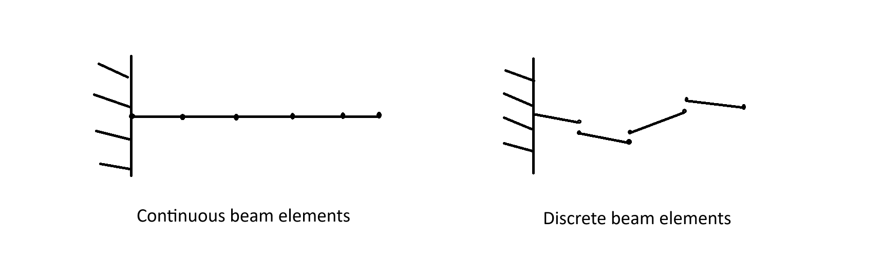
Beam reference line can be outside the structure. This happens when the structure has varying cross-sections. It is hard to know how much error it may introduce when the beam reference line is outside. One way is to have something called “discrete beam elements“ shown below, where elements are not connected to each other so each element can be placed inside the cross-section. Then continuity condition is enforced between elements. Do engineers usually use continuous beam elements like the one on the left or the discrete elements on the right?
For real life engineering problems, what is the best way to model a beam such that error from the 1D beam analysis is minimized? Thanks for your attention @Yu_Group
Regarding your question of #2: Could you please provide a bit more detailed information? For example, in what specific scenario is the beam reference line considered “outside” the structure? I am not entirely sure I understand what “outside” means here. Does it refer to a cross-section that is not a closed shape? Also, when you mention the error, do you have a specific field of interest for the measurement (e.g., displacement, stress/strain, or sectional force/moment resultants)? Nevertheless, I personally do not have experience with a case that use discrete beam elements (DBE), and usually lean to the continuous beam elements (CBE) and conventional FEA approaches such as those available in Abaqus and ANSYS. It would be interesting to see a comparison study, such as 3D vs CBE vs DBE, with consistent boundary conditions and load, to measure errors in the fields you are interested.
Thanks for the reply @fang.jiang !
For clarification:
Q1: What does “the beam reference line is outside“ mean?
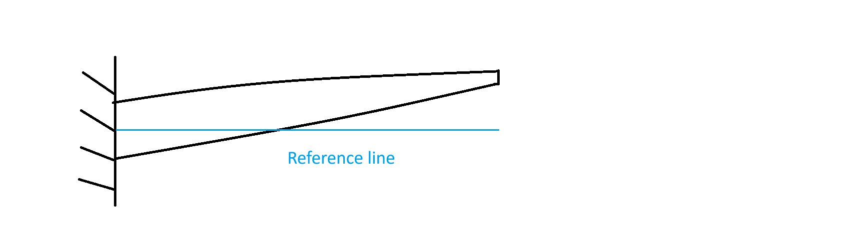
It means the reference line is outside the geometry, that is, there is no material at the reference line. One example can be seen below with a swept wing. If you choose the reference line at the centroid of the root, the beam reference line will go outside the geometry due to the sweep angle.
Q2: What does “error“ mean?
In general, it is displacement/stress values using cross-sectional analysis + beam analysis compared to a 3D analysis of the entire structure using 3D block elements for statics. For vibration, it is usually frequency that is compared.
It would indeed be interesting to have a comparison using continuous/discrete beam elements. The reason for this inquiry is that I am not sure how engineers in the industry use beam elements for the best accuracy possible. Based on what I have gathered from the literature, there is no general conclusion on this, and discrete elements are rarely used or studied.
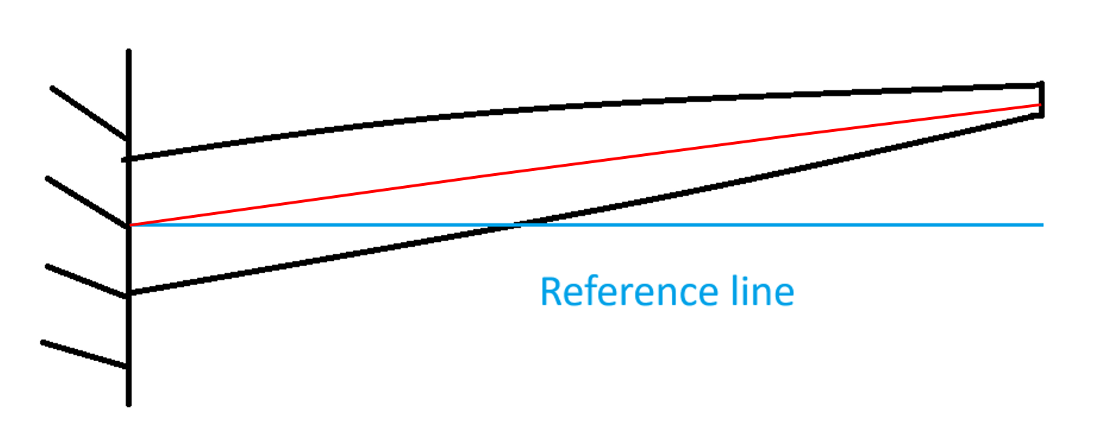
I would pick the reference line somewhere close to the red line below, for convenience, one of the elastic center, shear center, or mass center, depending on the beam topology and your interest on application scenarios.
However, for displacement and stress and strains in the three major directions except through-thickness directions, if your load application and recovery are consistent, I would not expect very big difference between using the blue and red reference lines from the above example, or from comparing the beam to 3D by using asymptotic approaches, unless some other factors are involved into the modeling. For frequency, you might find some higher order modes are changing there sequence by comparing beam to shell or 3D.
To be honest, the best accuracy is the 3D, IMO… When we simplify it into beams or shells, assumptions are made according to our application scenarios, meaning one set-up may work well for one scenario but not so good for some others where we will need to change our assumptions as well as the set-up…. hard to find one good for all, again that would be the 3D model if computational resource allows.
My feel of discrete element is that it is not so intuitive comparing to the continuous, making it a bit tricky to interpret the results for finding solutions during the practical endeavor.
It is part of our interest to see whether discrete beam reference line would produce a better result for beams with abrupt changes in cross-sections (like aircraft wings with ribs, the cross-section abruptly changes along the reference line where it goes from the cross-section with rib to the cross-section without the rib) so we can always put the reference line at the shear center etc based on one’s need. I am doing research on such discrete elements to see if it produces a more accurate result compared to a continuous reference line. Running a full 3D Finite Element Analysis (3D FEA) is usually too expensive for most companies, so we want to study how good a beam model can be, basically using it as a cheap alternative. The goal of the study is that, with given cross-sectional properties, how should we use the beam elements such that we can minimize the error compared to 3D FEA.
As for what you suggested with the red line, the cross-sectional analysis will be using an oblique angle.
@SichenLiu@Wenbin Obliqueness is a great point here, I personally also would like to see how this impact results, in light of the prebend and sweep geometry features seen in blade structures. Please kindly keep me posted on your findings.
Here I have a request for Sichen: could you please provide an example that shear centers on the adjacent sections change so much that drives you to use DBE?
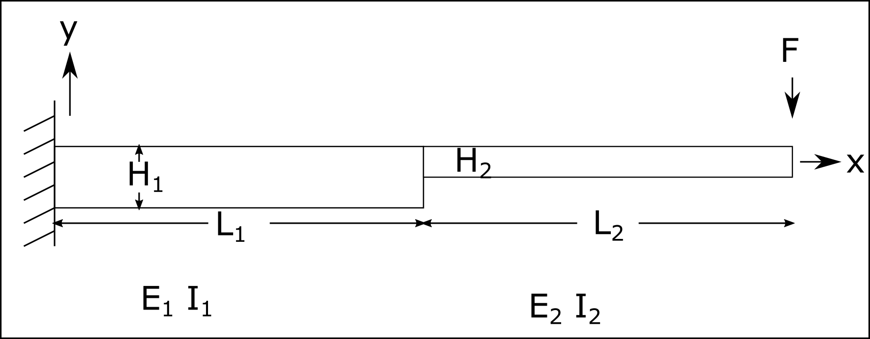
@fang.jiang do you mean an example in the form of VABS input and output files and show that shear center deviates a lot? I have not done such examples of rotor blades or aircraft wings yet and I am still trying to find a good benchmark problem to demonstrate this. If you want an example of this, the simplest, but not so realistic one can be stepped beams shown below, where shear center, extension center etc change abruptly at x=L1.
Right now the speculation that using discrete beam elements improves accuracy is purely hypothetical. I need to run some simulations to show if using discrete actually improves the result.
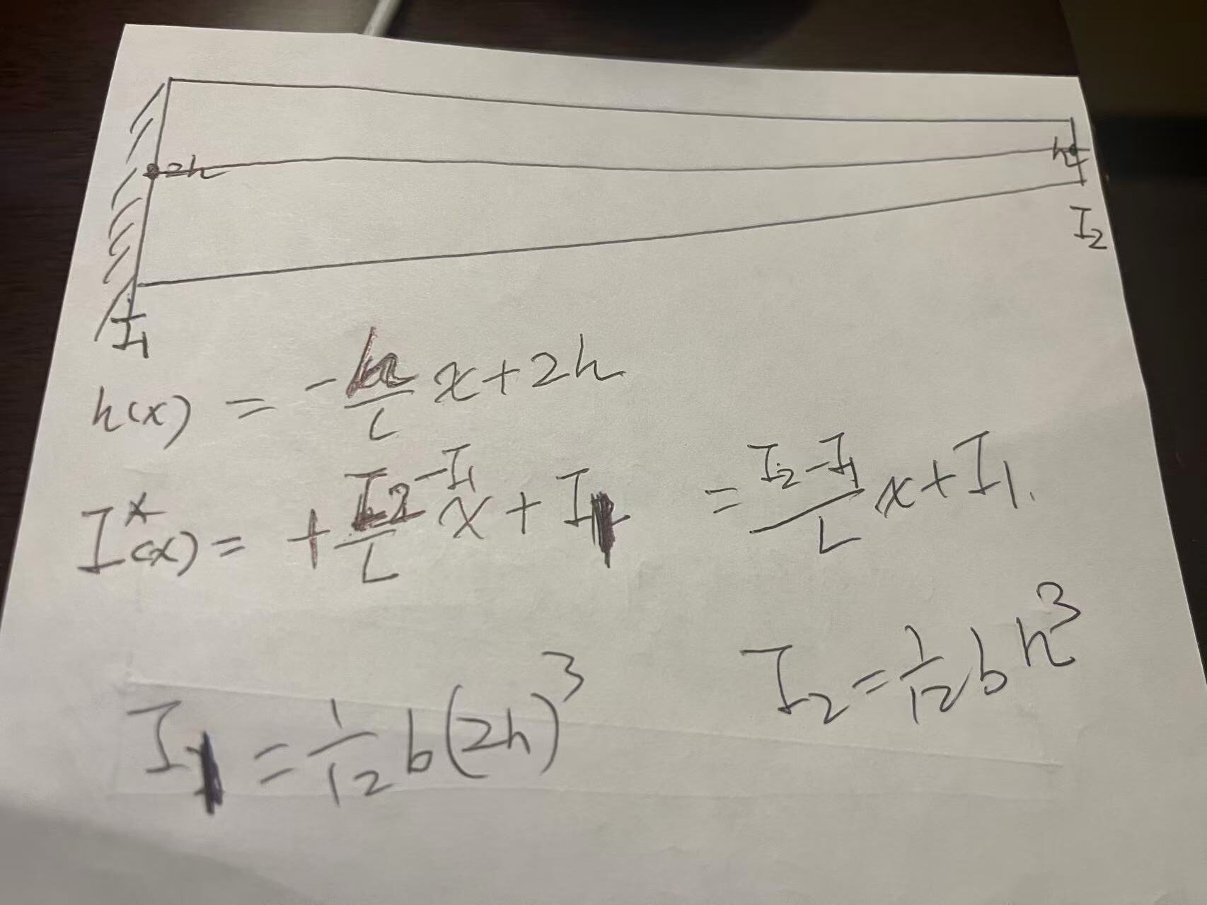
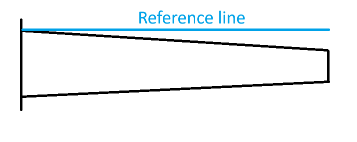
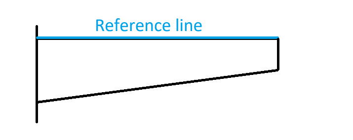
chose the top line as a continuous reference line, using I(x)=1/12 bh^3, with h=-h/Lx+2h.
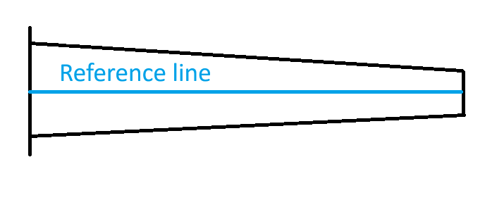
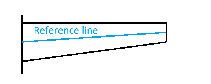
choose the center line as the reference, with I(x)=(I2-I1)/L*x+I1, with I1=1/12 b (2h)^3, I2=1/12 bh^3. This should be the industry practice according to Dr. @fang.jiang. Correct me if I am wrong.
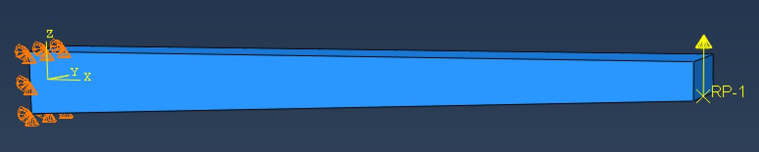
use 3D FEA.
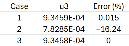
I expect 1 & 3 will give very close results as long as the beam is long enough. 2 will introduce significant error. You can plot the error with respect to the aspect ratio L/h.
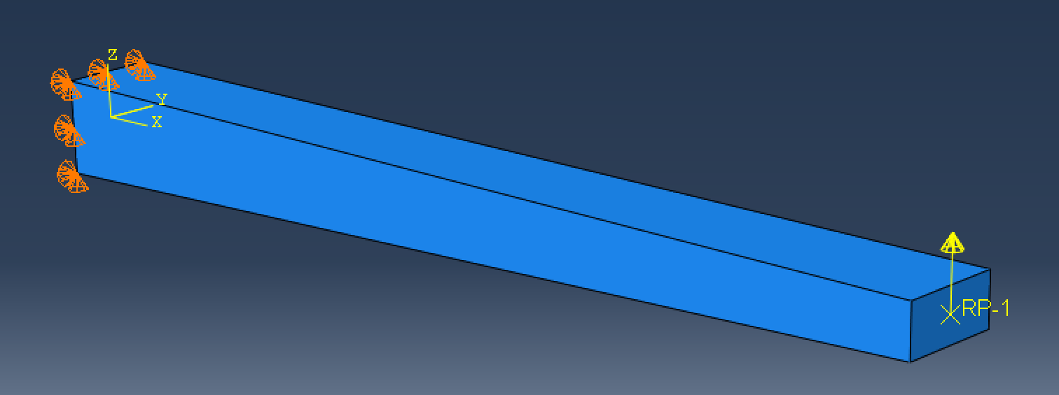
Using 3D FEA to compute displacement at the tip (where RP-1 is). Fix all DOFs at the root (shown in orange) and apply a concentrated force at RP-1 with F3=1000 (shown as the yellow arrow). Couple RP-1 with the entire surface at the tip.
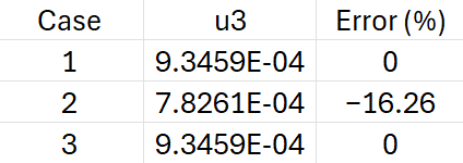
Here the error is the percentage error relative to the result from 3D FEA. This means a linear bending stiffness EI in the second case underestimate the displacement, which makes the beam stiffer.
Sorry my picture was not clear. My problem is not symmetric. The top surface is horizontal. Can you do that problem? That problem also captures possible error due to obliqueness. I suspect that the errors will even be bigger, which industry practice is far from being accurate.
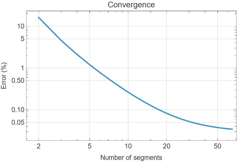
For option 2, also divide it to multiple segments (2,4,8,16,32), the error should decrease. At which number of segment, will it converge to exact results?
Can you divide the beam into segments to see the results? It might be too difficult to to do it analytically and tediously, you can use GEBT. GEBT uses linear interpolation of properties. You can divide it to be 8, 16, 32 segments to see the convergence. I suspects that with 32 segments, you should get pretty good results.
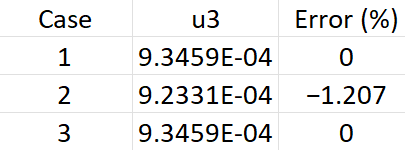
Now, change option 2 to be: divide the beam equally to four segments, compute I1, I2, I3, I4. Using these four values to interpolate to find I(x). This way, the results should be very close to option 1 and 3.
I used different number of segments (this is the number of cross-sections, e.g., number of segment = 2 means there is no divide, it is the same as the original option 2 where there are only 2 cross-sections and use a linear interpolation, and number of segment = 3 means there are 3 cross-sections with another one in the middle of the beam) to make this convergence plot:
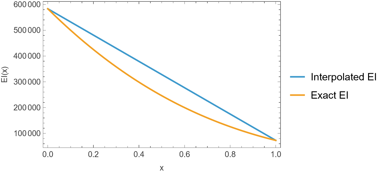
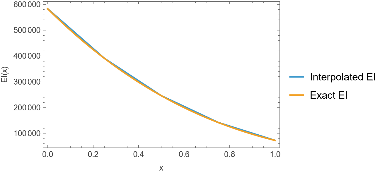
The rotation and curvatures are similar to displacement. Plots are similar to what I presented in the previous post. I think in this case linear elements are good enough because the real (exact) bending stiffness EI (even though it is cubic) are close to a linear function.
See the bending stiffness for 2 cross-section, 1 linear element, they differ a lot.
Make sense. However, our objective is to verify whether the current industry practice provides sufficient accuracy or not. For this case, it looks ok. We need to think about other realistic cases which linear interpolation might not work.
@fang.jiang I will be interested in seeing the situations that a beam model does not work for wind turbine blade structural design/analysis. Some might be related to the intrinsic limitation of a beam model, some might be related to incorrect use of a beam model, such as correct choice of reference line, computing and interpolation of sectional properties, computing/interpolation of beam loads, etc. These are several aspects that are not normally thought through.