Dear all,
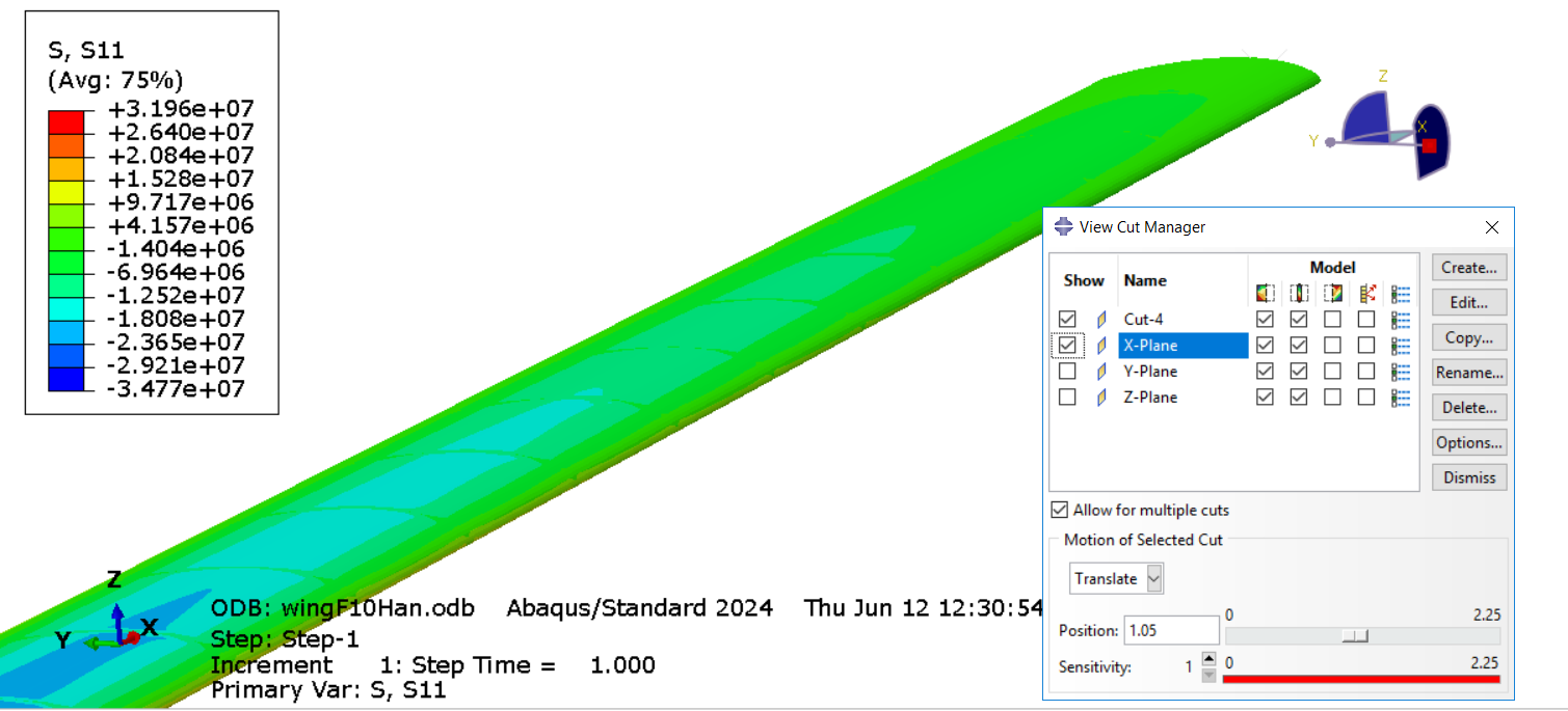
Is there an easier way to obtain the view cut for a full 3D model? The goal is to get the stress contour for the part from x=1.05 to x=1.2. Basically only visualize a part of the full 3D model.
I tried to use two cutting planes, one at x=1.05 (X-Plane) and another one at x=1.2 (Cut-4), as shown in the screenshot below, but what I got is not intersection (1.05<x<1.2) but union (x>1.05 and x<1.2) which shows up as the entire 3D model.
I also tried writing a script that collect all the nodes with x coordinate that satisfy 1.05<x<1.2 using the odb file, but the problem is the model (or the assembly) has multiple instances with millions of nodes, it takes a very long time, usually 10+ mins to run and is very error prone.
I would really appreciate any suggestions on this. @Yu_Group
What you get is the current design of the multiple cuts in which each cut portion added to the display (i.e., the union, not the intersection). Generally we rely on the display group function to display the contour plot for part of the model.
Hello Dr. Mao, thanks for your reply! I’ve played with display group, but it seems very difficult to select all elements that satisfy 1.05<x<1.2 as there is no option on Abaqus to specify that (in other words, I cannot put variable as x-coordinate, and specify the min value of x is 1.05 and the max value is 1.2). I looked up manual and found no method/function that functions like a bounding box for selection, thus I wrote a script to check x-coordinate for each node and define them as display group, which I mentioned in the original post.
Is there a better way to do this? Based on the given Abaqus manual it seems very tricky and needs a workaround.
Not sure if there is a more straight forward way, but I think you could try combining “view cut” and “display group” to achieve what you want. For each portion, use “view cut” to separate elements at the precise location you want and create a display group.
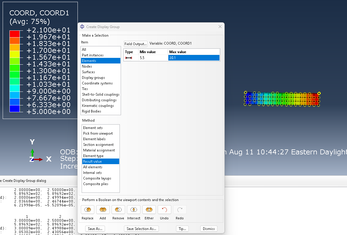
in creating display group, there is an method (bottom box) called “Result value”, i.e., selection based on Results. So, you can request COORD results output (which include nodal and element integration point COORD). Once they are in the ODB, you can create a display group (either elements or nodes)
@kmao24 Thanks for the idea Dr. Mao. I also looked into result values but it seems that I had to request it before running the job. I did not initially request it so it seems that I have rerun the simulation. Thanks for your help!
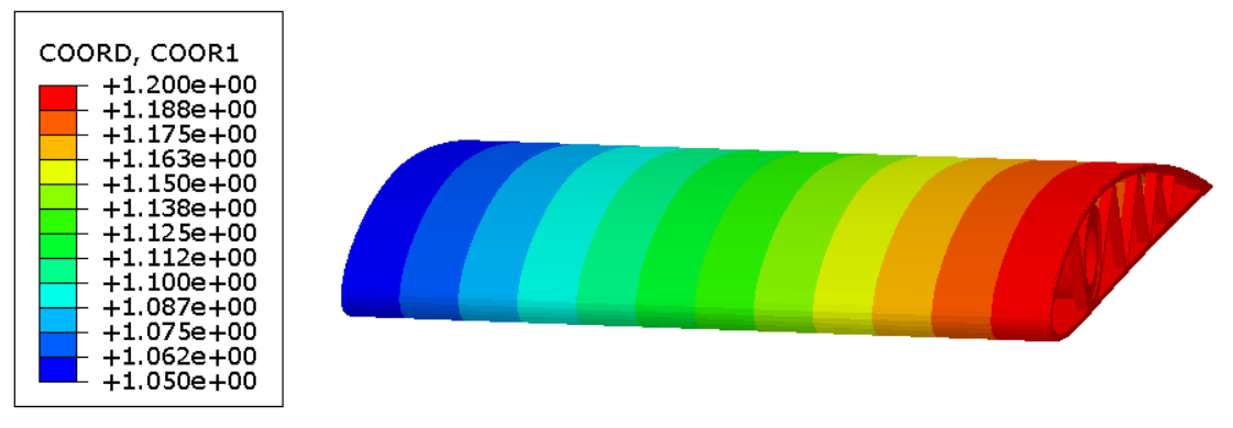
Using result value indeed can single out the elements whose x coordinate fall between the min and max value shown in your screenshot, so I tried this for my benchmark problem and used x coordinate (COORD 1) from 1.05 to 1.20 and obtained the contour plot below
Note:
The only problem is this select the entire elements, which means to make it a perfect cut, elements in x direction (spanwise direction for the beam) must be layered perfectly (in other words, a layer of elements must have exact same x coordinate in order to have a perfect cut, otherwise, this will result in an uneven cut at both ends, as seen in this example). This is usually not the case because different parts, like skin, spars, and ribs in this example, are created and meshed separately as separate Parts and assembled in the Assembly module.
The core issue is using result values does not cut the elements, so to solve this issue I found three ways (can be used altogether):
Specify edge seed along the span such that the nodes are located exactly at the cut (in my case x=1.05 and x=1.2). Note that I have to specify min value = 1.049 and max value = 1.201 to make the selection range bigger because of imprecision (often called floating-point imprecision) to ensure all desired elements are selected.
Use angle (need to define a degree) to select the entire layer of elements that are protruding from both ends and remove them in display group.
Use view cut on already selected elements, but this only cut off one side instead of both.
Yes, displaying a whole element (not a partial one) is what the display group is designed for. In your situation, as you said, you can use a combination of techiniques of the display group, model partition (at the cutting plane), and a single cutting plane to get a close approximation to what you intend to display.